Intro
In this blog, I discuss the fundamental laws and formulas governing electricity, their application, and why they are essential for circuit design in any electrical system. Whether you aspire to become an electrician, a PCB (printed circuit board) Design Engineer, or you are merely a hobbyist like me, I hope this post can help you gain some foundational understanding of the subject.
Electronic circuits are more integrated into our daily lives than ever before. Regardless of your background, location, or profession, you're almost certain to interact with them in some way. Understanding how electronic circuits work begins with grasping a few key concepts: voltage, current, resistance, power, and how they relate through fundamental laws like Ohm’s Law, Watt's Law, and Kirchhoff’s Law. These principles form the backbone of nearly all circuit analysis and design, from the simplest flashlight to the most advanced microprocessor.
Let's start with the basic units of measurement in electronics. In my explanation, I will use the analogy of water passing through a hosepipe to help visualise what these units represent and the role they play.
Units Of Measurement
V - representing voltage, measured in Volts (V)
Picture a garden hose: the water flowing through it is like an electric current, and the pressure pushing the water is analogous to voltage (volts). When the pressure is high (high voltage), more water (current) will want to flow through the hose. When the pressure is low (low voltage), the water slows down or stops flowing altogether.
I - representing current, measured in Amps (A)
If voltage is like water pressure, then current (amps) represents the amount of water flowing through the hose. When pressure (voltage) is high and the hose is wide (low resistance), a large volume of water flows, leading to a high current or more amps. Conversely, when pressure remains constant but the hose diameter decreases (increasing resistance), less water passes through, resulting in a reduced current or fewer amps.
R - representing resistance, measured in Ohms (Ω)
If we think of voltage as water pressure and current (amps) as the flow of water, then resistance is similar to the size or condition of the hose through which the water flows. A narrow hose, or one with kinks, blockages, or rough inner surfaces, indicates high resistance, restricting flow even at high pressure. Conversely, a wide, smooth hose signifies low resistance, enabling more water to pass through easily.
P - representing power, measured in Watts (W)
If voltage is representative of water pressure, then power (in watts) signifies the quantity of water used to water a plant. When both pressure (voltage) and flow rate (current) are high, a large volume of water is delivered quickly, resulting in more work being performed, which corresponds to high power. Conversely, if either pressure or flow is low, less water is delivered over time, resulting in lower power.
Next, we will examine the laws that govern the relationship between these measurements, their significance, and how they are used.
Ohm's Law
Ohm’s Law is fundamental to circuit design, as it defines the relationship between voltage, current, and resistance. It allows us to calculate values across components, verify how circuits operate, diagnose problems, and maintain proper regulation and balance within an electrical system. Just like controlling water flow from a garden hose prevents overwatering or bursting, controlling power in a circuit prevents overheating, component failure, or fires. Ohm's Law enables us to manage current, ensure proper voltage from power supplies, safeguard components, and select suitable wire sizes and ratings for safe, efficient operation.
The Ohm’s Law triangle (depicted below) is a practical visual tool that helps memorise and apply the relationships between voltage (V), current (I), and resistance (R) in an electrical circuit. It is divided into three sections, revealing three key formulas, with voltage positioned at the top and current and resistance at the bottom. To use the triangle, cover the value you need to find, and it will reveal the appropriate formula. The vertical centre line signifies multiplication, while the horizontal centre line indicates division. I have provided a brief breakdown of each formula below.
.png)
V = I × R
To calculate the required voltage to push a certain amount of current through a given resistance, we multiply the current (I) by the resistance (R).
I = V / R
To calculate the amount of current flowing through a circuit, we divide the voltage (V) by the resistance (R). This tells us how much current will flow when a certain electrical pressure is applied across a given resistance.
R = V / I
To calculate the resistance in a circuit, we divide the voltage (V) by the current (I). This tells us how much the circuit resists the flow of current when a specific voltage is applied.
Watt's Law
Watt's law enables us to calculate the amount of electrical power being used or generated within a circuit. It is essential for choosing power supplies, preventing overheating, and estimating energy costs. We can apply Watts' law both in small electronics and large-scale power systems. Like Ohm's Law, Watts' Law includes three essential formulas. As we will explore later in this blog, these formulas are interconnected and often used in combination with Ohm's Law.
Much like Ohm's Law, we have a Watts Law triangle (shown below), with the only difference being that voltage (V) is replaced by power (P). This visual aid illustrates the relationship between power (P), current (I), and resistance (R) in an electrical circuit. The use of the triangle format remains consistent, with the vertical centre line representing multiplication and the horizontal centre line representing division. As I did before, I have provided a brief breakdown of each formula below.
Much like Ohm's Law, we have a Watts Law triangle (shown below), with the only difference being that voltage (V) is replaced by power (P). This visual aid illustrates the relationship between power (P), current (I), and resistance (R) in an electrical circuit. The use of the triangle format remains consistent, with the vertical centre line representing multiplication and the horizontal centre line representing division. As I did before, I have provided a brief breakdown of each formula below.
.png)
P = V × I
To find the electrical power (P) in a circuit, multiply the voltage (V) by the current (I). This indicates the rate at which energy is used or generated when a specific current flows at a given voltage.
I = P / V
To find the current (I) in a circuit, divide the power (P) by the voltage (V). This calculation illustrates the amount of current required to produce a specific power output at a specified voltage.
V = P / I
To compute the voltage (V) in a circuit, divide the power (P) by the current (I). This indicates the electrical pressure required to supply a specific power level at a given current.
Kirchhoff’s Law
The third and final law covered in this blog is Kirchhoff's Laws. Kirchhoff's circuit laws consist of two principles that govern the conservation of current and energy in electrical circuits. They are commonly referred to as Kirchhoff’s Voltage Law and Kirchhoff’s Current Law. Below, I will provide a brief analogy for each law. However, if you want to explore these laws more thoroughly, I highly recommend watching this video.
Kirchhoff’s Current Law (KCL)
Kirchhoff’s Current Law states: "The total current going into a junction is equal to the total current coming out of that junction."
Again, using the hosepipe analogy mentioned earlier, picture a hosepipe with water flowing in and out. If 3 litres per second enter, then 3 litres per second must exit; otherwise, the pipe could burst or run dry. For example, if 2 A (amps) flow into a node and two wires exit, one might carry 1.2 A and the other 0.8 A, totalling the 2 A from the original source. (1.2A + 0.8A = 2A)
Kirchhoff’s Voltage Law (KVL)
Kirchhoff’s Voltage Law states: "The total voltage gained around any loop is equal to the total voltage lost in that loop."
In summary, KVL states that the total voltage around any closed loop is zero. Imagine a loop of hosepipe filled with water, with a pump pushing water through it in a circle. Along the way, sprinklers or valves oppose the flow, causing pressure drops. The pump increases water pressure by 10 units, like a 10-volt battery. As water flows through each sprinkler, it loses pressure, similar to a light bulb using up voltage in a circuit. The first sprinkler lowers pressure by four units, and the second by six units. In the context of an electrical circuit, this would be represented as (10V - 4V - 6V = 0V). To see this applied in a practical example, I recommend referring to the following video.
The Formula Wheel
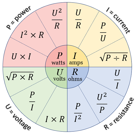
In this section, let's consolidate everything we have learnt so far, starting with the formula wheel. The formula wheel is an invaluable visual aid for referencing all of the most common power formulas. The wheel is divided into sections: power, voltage, resistance, and current, each containing three formulas. As I'm sure you noticed at a glance, we have all the formulas specified in Ohm's and Watts laws. However, interestingly, we also have some new additions I have yet to cover.
Previously in this blog, I mentioned that Watt's Law is often used in conjunction with Ohm's Law. These new formulas are simply shortcuts for performing multiple calculations using Watt's Law and Ohm's Law simultaneously. In the following section, I will summarise the formulas from Ohm's and Watt's Law, organising them into sections. We will have specific sections for calculating power, current, voltage, and resistance. Additionally, I will provide detailed breakdowns of the newly introduced formulas and how they work.
The Three Key Power Equations (Watts)
P = V × I
This initial formula should already be familiar, as it derives directly from Watts' law, which allows calculation of power using only voltage and current values. For example, if we have a voltage of 10V and a current of 2A, power will be equal to 20 Watts (10 × 2 = 20).
P = I² × R
Now, this is where things get interesting! This formula combines equations from both Ohm's and Watt's Law to help calculate power in a circuit when only the current and resistance are known. How does this connect to Ohm's and Watt's laws? Let's break it down using an example.
For this example, let's assume our values are: I = 2, R = 5
Since Ohm's law states that V = I × R, we have the required values to determine voltage. Using our example values, we find the voltage to be 10 (2 × 5 = 10). With the voltage now known as 10, we can use the formula P = V × I from Watts' law. Using the given current of 2, the power is calculated to be 20 Watts (2 × 10 = 20).
To summarise our calculations, we have done the following: I × R × I (2 × 5 × 2 = 20), which leads us to use the rearranged shorthand P = I² × R (2² × 5 = 20).
P = V² / R
This equation calculates the power in a circuit when only the voltage and resistance values are known. Based on the previous reasoning, it's not surprising that the formula P = V² / R has a similar explanation for its use. As we previously did, let's break it down with an example.
For this example, let's assume our values are: V = 20, R = 10
Since Ohm's law states that I = V / R, we have the required values to determine current. Using our example values, we find the current to be 2 (20 / 10 = 2). With the current now known as 2, we can use the formula P = V × I from Watts' law. Using the given current of 2, the power is calculated to be 40 Watts (20 × 2 = 40).
To summarise our calculations, we have performed the following steps: V / R × V (20 / 10 × 20 = 40), which leads us to use the rearranged shorthand P = V² / R (20² / 10 = 40).
The Three Key Resistance Equations (Ohms)
R = V / I
We should recognise the first formula because it originates from Ohm's law, and it is used to calculate power when only voltage and current values are available. For example, if we have a voltage of 8V and a current of 2A, the resistance will be equal to 4Ω (8 / 2 = 4).
R = V² / P
This new equation calculates the resistance in a circuit when only the voltage and power values are known. As we did for previous examples, let's break this formula down step by step.
Let's assume V = 3, P = 30
With voltage and power available, we first determine current using Watts' Law, which states that I = P / V. This gives us a current of 10A (30 / 3 = 10). Then, with the obtained current of 10A, we refer back to Ohm's Law, R = V / I, to find a resistance of 0.3Ω (3 / 10 = 0.3).
Note: In mathematics, parentheses ( ) indicate that the calculations inside them should be done first, following the PEMDAS rule.
To summarise our calculations, we have performed the following steps: V / (P / V) (3 / (30 / 3) = 0.3), which leads us to use the rearranged shorthand R = V² / P (3² / 30 = 0.3).
R = P / I²
This new equation calculates the resistance in a circuit when only the voltage and current values are known. Again, we will break this down into steps with an example.
For this example, let's assume P=100, I = 4
Watts' Law states that V = P / I, meaning a voltage of 25V (100 / 4 = 25). With the voltage established, we can now refer to Watts' Law, where R = V / I, giving us a resistance of 6.25Ω (25 / 4 = 6.25).
To summarise our calculations, we have performed the following steps: P / I / I (100 / 4 / 4 = 6.25), which leads us to use the rearranged shorthand R = P / V² (100 / 4² = 6.25).
The Three Key Voltage Equations (Volts)
V = I × R
We should already recognise this first voltage formula from Ohm's law, which allows us to calculate power when only voltage and current are known. For example, if the current is 2A and the resistance is 10Ω, the power will be 20 Watts (10 × 2 = 20).
V = P / I
Similarly, the second voltage formula should also look familiar from Watts' law; it allows us to calculate voltage when only the power and current values are known. For example, if power is 10W and the current is 0.5A, the voltage will be equal to 5 Volts (10 × 0.5 = 5).
V = √ P × R
The third voltage equation is another new addition, enabling the calculation of voltage in a circuit using only the power and resistance values. Once more, we will break this down into steps with an example.
For this example, let's assume P = 80, R = 20
In the earlier power equation, P = I² × R, we learnt to calculate power using only current and resistance. But in this case, since we know the power and resistance but not the current, we can rearrange the formula to solve for the current (I). We need to ask ourselves: what is the resistance (R) multiplied by to get the power value (P)? In other words, based on our example, what multiplied by 20 equals 80?
To find this out is quite simple: if you divide power by resistance, you will get the value of I². In formulaic terms, this would translate to I² = P / R. In our example values, this would mean I² is equal to 4 (80 / 20 = 4). Now all we need to do is find the square root of I (√ I). This means the value of I in our example will be 2 (√4 = 2).
Great! Now that we have the current (I) and resistance (R) values, we can apply Ohm's Law. According to Ohm's Law, V = I × R, so we substitute our numbers to find the voltage. Using our example, the voltage calculates to 40V (2 × 20 = 40).
To summarise our calculations, we have performed the following steps: √ (P / R) × R (√ (80 / 20) × 20). Ultimately, this leads us to use the far simpler shorthand V = √ P × R.
The Three Key Current Equations (Amps)
I = V / R
The first formula for calculating current, which we already know from Ohm's law, is used to calculate voltage when only the power and current values are known. For example, if the voltage is 5V and the resistance is 1Ω, the current will be 1A (5 / 1 = 5).
I = P / V
The second formula related to current, which we discussed in Watts's law, is used to find current when only power and voltage are known. For example, if the power is 60W and the voltage is 5V, the current will be 12A (60 / 5 = 12).
I = √ P / R
The last equation on our list calculates the current in a circuit when only the power and resistance values are known. Let's break down this final formula into steps with an example.
For this example, we will assume P = 60, R = 3
Similarly to the breakdown of V = √ P × R, we will need to do some reverse engineering to dissect this formula. Returning to the formula P = I² × R, we can once again examine this formula to determine the value of I. We once more need to ask ourselves: what is the resistance (R) multiplied by to get the power value (P)? In other words, based on our example, what multiplied by 3 equals 60?
As before, we will find the value of I² by dividing power by resistance: I² = P / R. Using our example values, this yields a value of 20. Following this, we will determine the square root of I² to get to the original value of I. In our case, this will be 4.47A rounded to 2 decimal places (√20 = 4.47).
To summarise our calculations, we have performed the following steps: √ (P / R) (√ (60 / 3)), landing us perfectly at the formula I = √ P / R.
In the next section, we will apply what we've learnt to real-world circuits. I will include a link here once it's released.